
Process Group
A Process Group gathers a set of steps into one container so a large model stays readable. The group keeps its member steps together, entities flow in and out through the routes that cross its boundary, and you can collapse it to a single box or expand it to work on the steps inside.
Grouping steps
Section titled “Grouping steps”Select the steps that belong together and make them a group. They become members of the container and move with it. Entities enter and leave through the routes that cross the group’s edge, so the flow through your model is unchanged; you have only drawn a boundary around a part of it.
Collapsing and expanding
Section titled “Collapsing and expanding”- Expanded, the group is a titled frame you can resize, with its member steps laid out inside for editing.
- Collapsed, it shrinks to a single box that shows how many steps it holds, with the crossing routes rerouted to the box. During a run the collapsed box shows a WIP: n pill for the work in progress inside.
Collapse a finished area to clear space, and expand it when you need to change what is inside.
Reading the work in progress
Section titled “Reading the work in progress”A collapsed Process Group shows a live WIP: n pill with how much work is inside. Set a WIP threshold to control when that pill turns from green to yellow to red, or leave it blank to let ProcessModel size it from the steps inside.
Group settings
Section titled “Group settings”Select a Process Group and its settings are on the General tab, under its name.
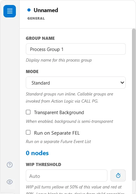
- Mode is Standard or Callable Subprocess. A Standard group runs inline, as part of the flow. A Callable Subprocess is run from action logic with
CALL PG "Name", optionally withASYNCorWITH attr = value(see Signals, Gates, and Other Logic). - Max Concurrent Calls appears for a callable group. It is the most calls that may run at the same time, and 0 means unlimited.
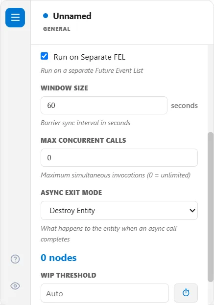
- Async Exit Mode appears for a callable group too. It says what happens to the entity when an async call completes: Destroy Entity or Route to Target. Choose Route to Target and an Async Exit Target box asks for the name of the node to route the entity to.
- Run on Separate FEL runs the group on a separate Future Event List, and its badge reads “Parallel FEL”. Window Size appears with it: the barrier sync interval in seconds, 60 to begin with.
A callable group wears a small pencil mark beside its name, and a group on a separate FEL a lightning bolt, on the expanded frame and on the collapsed box alike. Rest the pointer on a mark to read its note. PM Optimizer cannot run an experiment on a model while a group has Run on Separate FEL turned on: turn it off to run one.
A group that holds only unit operations, which its box marks as a skid, does not offer Mode, Run on Separate FEL or WIP Threshold.
LegacyHow this worked in the previous version
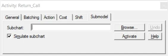
The submodel tab (shown below) allows you to reference a subprocess chart when you are creating hierarchical models. All activities have a submodel tab in their properties dialog. For more information, see Hierarchical Modeling.
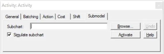
Subchart If the activity is to be linked to a subprocess, enter the name of the subchart file defining the subprocess.
**Simulate subchart **If a subchart is defined, it may be ignored for a particular run by unchecking this option. If checked, information defined for the activity is ignored as control drops to the subchart.
**Activate **If a subchart is defined, that chart will be opened. If a new name is entered into the Subchart field a new blank model will be created and activated.
Submodel tab will not show on 50 object licenses.
Hierarchical modeling
Section titled “Hierarchical modeling”Hierarchical modeling is a modeling approach in which one activity in a model represents entire process. These processes are defined themselves as models in separate chart files which are linked to the activities representing them. A model that is linked to an activity in another model is referred to as a submodel. Submodels themselves may have activities representing other submodels in a hierarchical fashion (see figure below).
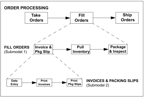
When a simulation is run on the general model, linked submodels are also simulated as part of the entire model. Optionally you can disable any or all of the submodels and use the generalized time defined for the activity representing the submodel. Submodels can also be run independently to facilitate the building and verifying of submodels.
A hierarchical modeling methodology has the following advantages:
Section titled “A hierarchical modeling methodology has the following advantages:”- It allows you to focus attention on smaller, more manageable components of a process step. If a component is still too complicated, it
- can be further divided into smaller components until each module is of manageable size.
- It reduces the risk of forgetting details of more complex modules, and confusing the interactions between modules.
- Provided interactions are carefully defined in advance, several modelers can work simultaneously on a modeling and simulation project, since they can each work on different submodels.
- It is easy to implement changes and corrections, as they should be made in one or a few simple submodels.
- The modular structure enables partial testing of a model, i.e. testing component by component.
- The modularly developed model is extremely convenient for documentation purposes.
- The modular hierarchical approach enables the modeling of components that can be used in different models, not just in the models for which they were developed.
Submodels can be physical operations or simply used as ways to perform calculations or do complex decision making. A submodel may take simulated time or could be performed in zero time. All activity and route times could be set to zero and might only be used to set conditions, make calculations or write out statistics under varied conditions.
Benefits of Using Hierarchical Modeling
Section titled “Benefits of Using Hierarchical Modeling”Any number of hierarchical levels can be defined and any model can have any number of submodels, although the same model may only be referenced once in a model hierarchy. Hierarchical modeling provides the following benefits over single level modeling:
- Simplifies the steps to visualize large processes.
- Provides a structured way to organize a model.
- Permits reuse of common submodels.
- Enables people to work on portions of the same model without interfering with each other.
Defining Hierarchical Models
Section titled “Defining Hierarchical Models”Four Easy Steps
Section titled “Four Easy Steps”Defining hierarchical models in ProcessModel is easy. It is a simple four-step process. These steps are listed below and explained in detail throughout this section.
- Create the main model chart.
- Create a submodel chart.
- Reference the submodel chart from the main model.
- Name all input and output connections of the representative activity in the main model with the same names as the corresponding connections in the submodel.
How It Works
Section titled “How It Works”With the activity connections in the main model mapped by name to connections in the submodel, entities arriving or routing to the activity in the main model will actually enter the activity in the submodel that has an input connection with the same name as the arrival or routing connection in the main model. The entity remains in the submodel until it encounters a routing having the same name as an output routing from the representative activity in the main model (see diagram on the following page). Entities can also be allowed to exit the system from within a submodel or go to lower submodels. Where appropriate, the same name can be assigned to multiple connections in a chart.
Creating the Main Model Chart
Section titled “Creating the Main Model Chart”By definition, the main model is the model one level higher than the submodel in the hierarchy. If you have more than two levels, a submodel to an upper level may also be the main model to a lower level in the hierarchy. The only thing that distinguishes the main model from any other model is that at least one activity has been selected to represent a submodel, with the submodels chart file referenced in the Submodel tab of the properties dialog.
Usually, the main model defines a process in general terms, the representative activities having a generalized time specified. The representative activity is only executed when you opt to disable submodels in the Simulation/Options dialog. When the model is simulated with the submodels, the representative activity is ignored and the detail of the submodel is executed.
Creating the Submodel Chart
Section titled “Creating the Submodel Chart”To create a sub chart, simply begin a new flowchart in ProcessModel and place the activities, connections, and any other objects, defining the submodel on the layout.
Then enter the necessary data in the properties dialog for each object and save the file. You can graphically link each sub chart to the main chart so that a right-mouse click will move you from one level to the next.
How To - Create a Link to a Submodel
Section titled “How To - Create a Link to a Submodel”- Open the SubModel tab for the process that will be represented by a subprocess.
- From the Submodel tab, select the Browse button to link to an existing submodel or type in a new name to create a submodel.
- Select the Activate button to move to the submodel.
-
Submodel tab will not show on 50 object licenses.
-
If you are linking to an existing submodel, you will now see that model. If you are creating a new submodel, you will now see a blank layout. Build the subprocess on this layout.
-
Name the connecting routes. For more information on naming connecting routes see “Connection Naming” below.
-
Submodels may be created independently and linked at a later time by linking to an Existing File, however, it is helpful to create the overall structure of the model at the beginning of the modeling project.
-
Saving and exiting from the subprocess will return you to the main process.
-
Always travel down to a submodel by using the activate button and close submodels when moving to a higher-level model. The opening and closing of the models force the update of Attributes and Variables in each model (i.e. the variables and attributes will be copied in both directions so that all action logic can be executed).
-
Always travel down to a submodel by using the activate button to make changes. Do not make changes directly to the submodel by opening it without opening from the main model.
Arrivals in the Submodel Chart
Section titled “Arrivals in the Submodel Chart”You can create a submodel with its own entities and arrivals if you want to test it independently. Arrivals get automatically replaced with inputs coming from the main model when linked into another model unless no routings or arrivals in the main model map to the arrival in the submodel.
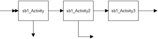
Remember that the routing of entities coming into the submodel from the main model is controlled by the routing or arrival defined in the main model. Likewise, the routing of entities coming from the submodel into the main model is controlled by the routing defined in the submodel.
Naming Variables and Attributes
Section titled “Naming Variables and Attributes”When naming attributes and variables to be used in a model that will use hierarchical models, you should give each attribute and variable throughout the model a unique name to avoid confusion and unexpected results. Keep in mind that all variables are global. If you define the same attribute or variable in a submodel that was defined in the main model, there will be only one attribute or variable, and it may be used throughout the entire model.
So if you are creating complex models using hierarchical modeling, you may want to establish some internal naming conventions, especially where teams are involved in the modeling project.
Delete Attributes and/or Variables and/or Scenario Parameters
Section titled “Delete Attributes and/or Variables and/or Scenario Parameters”Linked hierarchical model files synchronize data when you save each file. When you delete a variable, attribute, or scenario parameter in one model file, it is added back in from the other linked files during synchronization.
- Unlink your hierarchical model files.
- Make your change in each file and save it.
- Re-link the hierarchical structure
Connection Naming
Section titled “Connection Naming”Once you establish representative activities and reference them to the sub chart, you need to name the connections into and out of the representative activity in the main model that will route to or from activities in the submodel. Then you need to assign matching names to the corresponding connections in the submodel.
The Name tab on the properties dialog for arrival and routing connections allows you to give the connection a name.
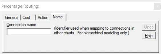
Connection name: The name of the connection. Connections that route entities to the submodel or back to the main model may have the same name, but there can only be one connection to which the entities are routed as shown in the illustration below.
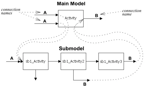
When using a submodel, remember that the connection from which the entity is routed is executed. The connection to which the entity is routed is ignored during simulation. In other words, in the above example, the A connections will use properties dialog information from the main model and the B connections will use the properties dialog information from the submodel.
- When using more than one submodel, connection names must be unique between submodels or an error will occur when the model is simulated. Keep your names simple to avoid misspelling names (yes that was on purpose) between levels.
Data Visibility
Section titled “Data Visibility”Model items such as resources, attributes, variables, scenario parameters, etc. are available to all “linked” model files. Therefore, if the simulation is started from the main model, all submodel items will be available to all other submodels in the hierarchical structure.
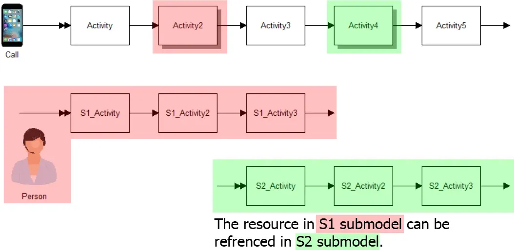
On the other hand, if the simulation is started from a submodel, only the items from that submodel and the submodels it calls will be available. Any items from submodels outside the hierarchical structure will not be seen.
Things to Remember
Section titled “Things to Remember”Simulation Displays the Wrong Submodel
Section titled “Simulation Displays the Wrong Submodel”When running a simulation, the same submodel is shown instead of showing the correct submodel file. To correct this situation:
- Close ProcessModel.
- Using Windows Explorer (or My Computer) browse to the folder containing your model files.
- Delete all files ending with a .emf extension. If you don’t see the filename extensions you can view them by clicking Tools / Folder Options / View, and uncheck the box labeled “Hide extensions for known file types”.
- Open ProcessModel.
- Open your main model and simulate it
Length of Submodel Path
Section titled “Length of Submodel Path”The maximum number of characters allowed when defining submodel links is 250. If your path (including the filename) is longer than that, you must move the file to a folder higher in the folder structure or shorten the folder names.
Using Attach Routes to Connect to Submodels
Section titled “Using Attach Routes to Connect to Submodels”An Attach route cannot be used to call a submodel or return from a submodel. Attaches must be done before leaving the main model or before returning from the submodel.
Advanced Hierarchical Modeling
Section titled “Advanced Hierarchical Modeling”ProcessModel has many unique capabilities not found in other simplistic modeling tools. ProcessModel allows complete control over the entry and exit points of a submodel. This means that a submodel can be very robust, having its own arrivals in addition to the entries that it receives from the upper level. It also means that exits from a submodel are not required to go to the same place in the upper-level model.
Send Submodel Entities to Different Main Activity Destinations
Section titled “Send Submodel Entities to Different Main Activity Destinations”It is often desirable to separate entities in a submodel and then because of that separation send them to different places in the main model or ultimately to another submodel.
In the example above, entities that leave the submodel from the activity sub1_Activity5, will enter into Activity3 at the main level. If Activity3 had a submodel attached then the entity would arrive directly to that submodel.
Sequential Activities Have SubModels Attached
Section titled “Sequential Activities Have SubModels Attached”If a model has activities in sequence that have submodels, then the name of the output route of the first submodel becomes the name of the input of the second submodel, etc.
The First (or last) Activity of Multilevel Models Each Have a SubModel
Section titled “The First (or last) Activity of Multilevel Models Each Have a SubModel”If a model is more than two levels and the first activity of each level has a submodel, then a modification needs to be made to the third level of the model so that the routing names will work. At the third level and beyond an activity needs to be inserted so that unique routing names may be used. This inserted activity will not effect the performance or output of the model if the time is set to zero and the statistics are unchecked (turned off). A simple small graphic may be exchanged for the “inserted activity” to take up space and not confuse the audience. The following example shows a three level model with an inserted activity to allow the first activity to have its own submodel.